Henry Ott Consultants
Electromagnetic Compatibility Consulting and Training
Slots in Ground Planes
The most important thing that I can say about slots in ground planes,
is don't have them! If you do have slots, no traces
can cross over them. If a trace does cross over the slot ask
yourself
this question: Where is the return path for the current?
Remember the fundamental principal of EMC, "return currents locally
and compactly, through the smallest loop area possible." If
everyone
would follow this principal, a great many of our EMC problem would go
away
or at least be minimized.
 The
lowest impedance signal return path is in a plane directly under the
signal
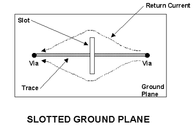
trace. Slots in ground planes divert the ground current
flow
(see figure), thereby producing a high ground impedance (Inductance)
and
a ground plane voltage drop that is the cause of increased emissions
from
the cables connected to the board. In addition, ground plane
slots
will significantly increase the crosstalk between traces that
cross
over them, and the larger loops formed by the return current paths will
radiate.
The table below shows measured values of ground plane voltage with
and
without a slot in the ground plane. The voltage measurements were
made between two point on the ground plane one inch apart and directly
underneath the trace. The slot was cut perpendicular to the
direction
of current flow, as shown in the figure, and half way between the
measuring
points. The entry under "holes" represents a linear pattern of
fifteen
holes each 0.052" in diameter (oriented perpendicular to current flow)
covering a linear distance of one inch. This is
representative
of an array of holes for vias or thru-hole component leads. The
voltage
measurements were made with a 10 MHz, 3 nS rise time clock signal
flowing
down the trace and returning in the ground plane. As can be seen
the array of holes did not increase the ground plane voltage, but the
slot
did increase the voltage by a factor of as much as five in the case of
the 1 1/2" slot.
Finding these problems, after-the-fact, on a buried ground plane
that
cannot be seen is a difficult and time consuming problem. There
is,
however, a very simple way to initially check the quality of the ground
plane. When you have printed circuit boards made, ask to have one
set etched but not laminated. That way, you can look at the
unlaminated
ground plane and see if there are problems very quickly. It would
be a good practice to do this with all new designs.
|
Length of Slot
|
Ground Plane Voltage
|
|
0 inches
|
15 mV
|
|
1/4 inch
|
20 mV
|
|
1/2 inch
|
26 mV
|
|
1 inch
|
49 mV
|
|
1 1/2 inches
|
75 mV
|
|
Holes
|
15 mV
|
© 2001/2000 Henry W. Ott
Return to top of page.
Return to HOC home page.
Henry Ott Consultants
48 Baker Road Livingston, NJ 07039
Phone: 973-992-1793, FAX: 973-533-1442
July 16, 2002