Henry Ott Consultants
Electromagnetic Compatibility Consulting and Training
Measuring Common-Mode Currents on Cables
The radiation from a cable is directly proportional to the common-mode
current on that cable. The common-mode current is the unbalanced
current (current not returned) on the cable. If this current is
not
returned on the cable, where does it go? Into radiation, that's
where!
In the case of intentional signals that flow down one wire of the cable
and return on another wire, the net current is zero.
Since cables are always a major source of product radiation,
measuring
the common-mode current is one of the most useful thing that you can
learn
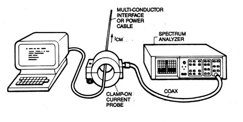
to do. The common-mode current can easily be measured with a high
frequency clamp-on current probe (such as the Fischer
Custom Communications Model F-33-1) and a spectrum analyzer, as
shown in the figure below. The F-33-1 current probe has a flat
frequency
response from 2 to 250 MHz. The transfer impedance of the current
probe is five ohms (+ 14 dB), therefore, a one microamp current will
produce
a five microvolt output voltage from the current probe.
 Make
it a habit to measure the common-mode currents on all your
cables.
Do it early on prototype models (while it is still easy to make a
change
to the product), and prior to performing EMC compliance testing.
If you fail the common-mode current test you will also fail the
radiated
emission test.
For a Class B product, the current must be less than 5 microamps (15
microamps for a Class A product). Use the above limits for cables
that are one meter or longer. For cables shorter than one meter,
the allowable current can be increased proportional to how much the
cable
is shorter than one meter. For example, for a half-meter long
cable
the maximum current would be 10 microamps for a Class B product (30
microamps
for a Class A product).
This technique works equally well on shielded or unshielded
cables.
This is also a good way to determine the effectiveness of your cable
shield
termination. If you use common-mode filters on your cables or use
ferrite cores to suppress common-mode radiation the current probe
measurement
will indicate their effectiveness. Just measure the current
before
and after inserting the filter (or ferrite).
All cables should be measured regardless of their
intended
purpose. Measure the signal cables, the power cord (ac or dc),
fiber
optic cables, monitor cables, I/O cables, telecom cables, and any other
cables that are attached to the product. If it's connected to the
product it can be a source of radiation!
What you want to do is reduce the common-mode current on each
cable to below 5 microamps (15 microamps for a Class A product).
The cables will interact. If you reduce the common-mode
current
on one cable, it will often increase on another cable.
Test Procedure: Monitor one cable at a time with
the common-mode current clamp. Use common-mode filters,
ferrite
chokes, cable shields, etc. to reduce the current to under 5 uA (15 uA
for a Class A device) then go on to the next cable. When you get
through all the cables, start over again, since the currents may
have increased on some of the previously fixed cables. Keep this
iterative process up until the currents on all the cables are
under
5 uA (15 uA for a Class A device). You may have to go through the
process two or three times on each cables. When you are finished,
the current on each cable should be under 5 uA (15 uA for a Class A
device)
and the cables should no longer present a problem when you do a
radiated
emission test.
Of all the various types of EMC measurements that you could
possibly
do, the common-mode current measurement is the most useful -- learn
to do it, and do it often.
© 2000 Henry W.
Ott
Henry Ott Consultants
Additional information on this plus other simple EMC measurements
(both
emission and susceptibility), that can easily be performed in your own
laboratory, is contained in our one-day course on Workbench
EMC Measurements.
For more information on the Model F-33-1 common-mode current probe,
contact Fischer Custom
Communications,
2917 West Lomita Boulevard, Torrance, CA, (310) 891-0635, FAX (310)
891-0644,
e-mail: Sales@Fischercc.com.
Correspondence
-
I followed your recommendation and bought a current probe to help debug
a cable radiated noise, which saved me a number of trips to the OATS
(Open
Area Test Site). [e-mail from a Ph.D in Canada]
Return to top of page.
Return to HOC home page.
Henry Ott Consultants
48 Baker Road Livingston, NJ 07039
Phone: 973-992-1793, FAX: 973-533-1442
February 20, 2004
 Make
it a habit to measure the common-mode currents on all your
cables.
Do it early on prototype models (while it is still easy to make a
change
to the product), and prior to performing EMC compliance testing.
If you fail the common-mode current test you will also fail the
radiated
emission test.