Henry Ott Consultants
Electromagnetic Compatibility Consulting and Training
Distinguishing Betweem CM and DM Conducted Emission
When diagnosing conducted emission problems, it is helpful to
distinguisg between the common- and differential-mode emissions. This
is desirable, because different power supply components affect
differential-mode noise than those that affect common-mode noise.
Similarly different components of the power-line filter suppress
differential-mode noise, while others suppress common-mode noise.
Knowing which mode is predominate in a product's conducted emission
spectrum basically divides the problem in half. Performing the
conducted emission test as specified by the various EMC regulations,
only measures the total noise and provides no clue as to whether the
predominate noise is common- or differential-mode.
 The figure to the left (Ott, H. W., Electromagnetic Compatibility Engineering,
John Wiley & Sons, 2009, page 705) shows a product's power supply
connected to a LISN (represented by two 50 Ω resistors), with both
common-mode and differential-mode noise currents emanating from the
power supply.
The figure to the left (Ott, H. W., Electromagnetic Compatibility Engineering,
John Wiley & Sons, 2009, page 705) shows a product's power supply
connected to a LISN (represented by two 50 Ω resistors), with both
common-mode and differential-mode noise currents emanating from the
power supply.
The noise voltage produced on the phase side of the LISN will be
Vp = 50 (ICM + IDM).
The noise voltage produced on the neutral side of the LISN will be
Vn = 50 (ICM - IDM).
Adding the phase and neutral voltages gives
Vp + Vn = 50 (2 ICM) = 2 VCM.
Subtracting the phase and neureal voltages gives
Vp -Vn = 50 (2 IDM) = 2 VDM.
Therefore, one can determine the common-mode and differential-mode
noise voltages individually by adding or subtracting the two LISN
voltages respectively.
This addition and/or subtraction of the two LISN voltages, however,
cannot be done after the measurement has been made, because the
measurement is just a magnitude, and does include the phase
information. The addition and/or subtraction of the two voltages must
be done before the phase information is lost. Therefore, what is
required is a network that adds or subtracts the two voltages before
they are measured–and, therefore, before the phase information is
lost.
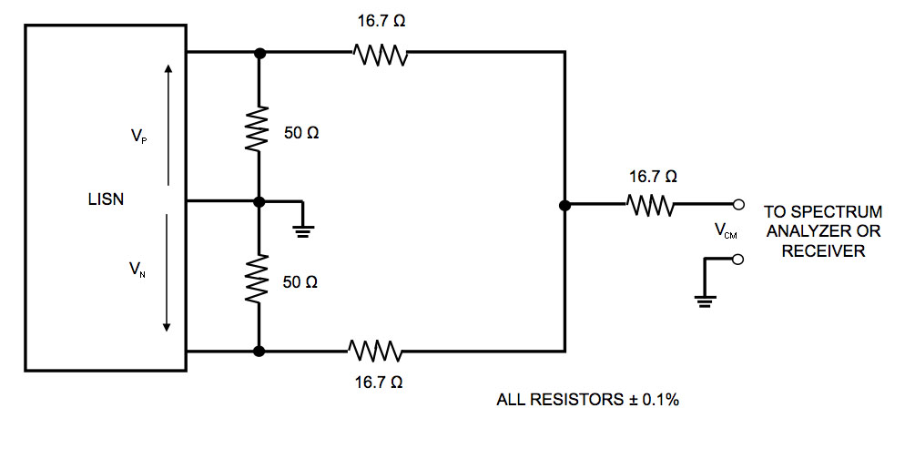 One simple network for doing this, often referred to as a LISN MATE (Nave, M. J. Power Line Filter Design for Switched-Mode Power Supplies, Van Nostrand Reinhold, 1991), consists of only five resistors as shown in the figure to the right (Ott, H. W., Electromagnetic Compatibility Engineering,
John Wiley & Sons, 2009, page 706). This network adds the two input
noise voltages together so that the output represents only the
common-mode noise voltage. Therefore, it is referred to as a
differential-mode rejection network. To achieve sufficient
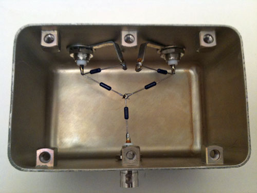
differential-mode rejection, the resistors used must be 0.1%, and laid
out carefully. A picture of such a network is shown below.
One simple network for doing this, often referred to as a LISN MATE (Nave, M. J. Power Line Filter Design for Switched-Mode Power Supplies, Van Nostrand Reinhold, 1991), consists of only five resistors as shown in the figure to the right (Ott, H. W., Electromagnetic Compatibility Engineering,
John Wiley & Sons, 2009, page 706). This network adds the two input
noise voltages together so that the output represents only the
common-mode noise voltage. Therefore, it is referred to as a
differential-mode rejection network. To achieve sufficient
differential-mode rejection, the resistors used must be 0.1%, and laid
out carefully. A picture of such a network is shown below.
In use, the conducted emission test is done first without the
differential-mode rejection network, to obtain the total conducted
noise voltage (common-mode plus differential-mode). If the product
passes, you are done.
If not, the test can be repeated with the differential-mode rejection
network placed between the two LISN outputs and the measuring device,
to obtain the common-mode conducted noise voltage. The difference
between the two readings must then be the differential-mode conducted
noise voltage.
© 2011 Henry W.
Ott
Henry Ott Consultants
Return to top of page.
Return to HOC home page.
Henry Ott Consultants
48 Baker Road Livingston, NJ 07039
Phone: 973-992-1793, FAX: 973-533-1442
August 29, 2011