Multiple A/D Converter Grounding Issues
Question: In
a 12-layer PCB (maximum clock frequency 112 MHz) I have 3 D/A
converters and 2 A/D converters. The A/D converter is a 14-bit
high-resolution device. During testing I found very high noise
levels on the PCB. While looking for a technique to minimize noise, I
came across your article (techtips/split-gnd-plane.html)
which talks about solidly connecting the analog and the digital ground
planes together under all the A/D and D/A converter chips.
I have two questions about the use of the above approach for 14-bit resolution A/D converters.
1. How to connect the AGND and the DGND pins of the A/D converter?
a. Should AGND and DGND be connected together and connected to the analog ground plane, or
b. Should the DGND be connected to the digital ground plane, and the AGND connected to the analog ground plane?
2. a. Should the analog ground plane and the ground digital plane be connected individually back to the power supply, or
b. Should only the digital ground plane be connected back to the power supply?
Answer: To understand my recomended approach better, and the reasons for it, I suggest that you read my June 2001 Printed Circuit Design article.
1a. Yes. A/D and D/A converters and most other mixed-signal ICs should be considered as analog components. These chips should always be referenced and decoupled to the analog groung plane. The pin names AGND and DGND refer to where these pins are connected internally and not to where they should be connected externally.
1b. No.
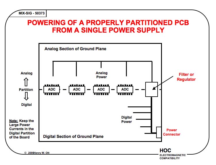
2a. No. The power should enter the board in the digital partition and be fed directly to the digital circuitry, and then filtered or regulated to feed the analog circuitry, see figure below.
2b. Yes.
I have two questions about the use of the above approach for 14-bit resolution A/D converters.
1. How to connect the AGND and the DGND pins of the A/D converter?
a. Should AGND and DGND be connected together and connected to the analog ground plane, or
b. Should the DGND be connected to the digital ground plane, and the AGND connected to the analog ground plane?
2. a. Should the analog ground plane and the ground digital plane be connected individually back to the power supply, or
b. Should only the digital ground plane be connected back to the power supply?
Answer: To understand my recomended approach better, and the reasons for it, I suggest that you read my June 2001 Printed Circuit Design article.
1a. Yes. A/D and D/A converters and most other mixed-signal ICs should be considered as analog components. These chips should always be referenced and decoupled to the analog groung plane. The pin names AGND and DGND refer to where these pins are connected internally and not to where they should be connected externally.
1b. No.
2a. No. The power should enter the board in the digital partition and be fed directly to the digital circuitry, and then filtered or regulated to feed the analog circuitry, see figure below.
2b. Yes.